Shear force and bending moment diagram of simply supported beam can be drawn by first calculating value of shear force and bending moment. Shear force and bending moment values are calculated at supports and at points where load varies.
Simply Supported Beam with Point Load Example
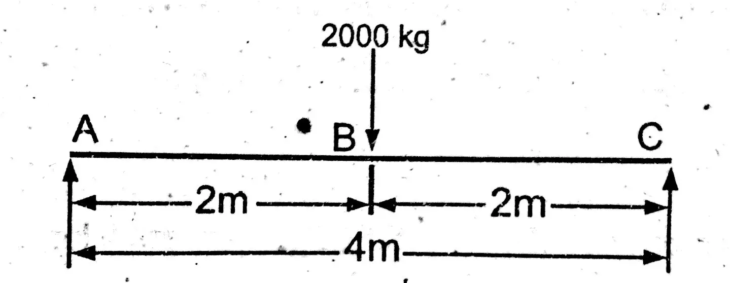
Draw shear force and bending moment diagram of simply supported beam carrying point load. As shown in figure below.
Solution
First find reactions of simply supported beam.
Both of the reactions will be equal. Since, beam is symmetrical. i.e.,
R1 = R2 = W/2 = 1000 kg.
Now find value of shear force at point A, B and C.
When simply supported beam is carrying point loads. Then find shear force value in sections. Shear force value will remain same up to point load. Value of shear force at point load changes and remain same until any other point load come into action.
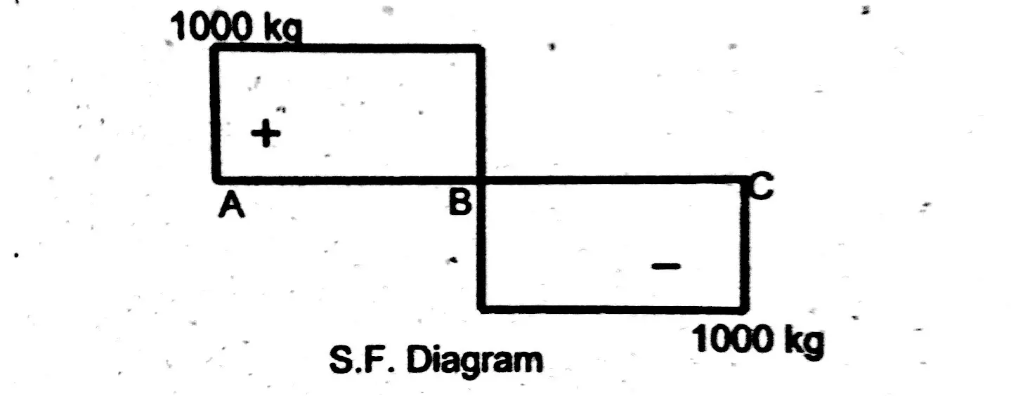
Shear force between ( A – B ) = S.F (A-B) = 1000 kg
Shear force between (B – C) = S.F (B -C) = 1000 – 2000
S.F (B – C) = – 1000 kg.
Shear Force Diagram
Bending Moment
In case of simply supported beam, bending moment will be zero at supports. And it will be maximum where shear force is zero.
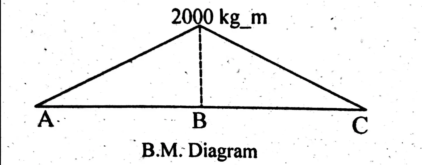
Bending moment at Point A and C = M(A) = M(C) = 0
Bending moment at point B = M(B) = R1 x Distance of R1 from point B.
Bending moment at point B = M (B) = 1000 x 2 = 2000 kg.m
Bending Moment Diagram
Simply Support Beam with UDL & Point Load Example
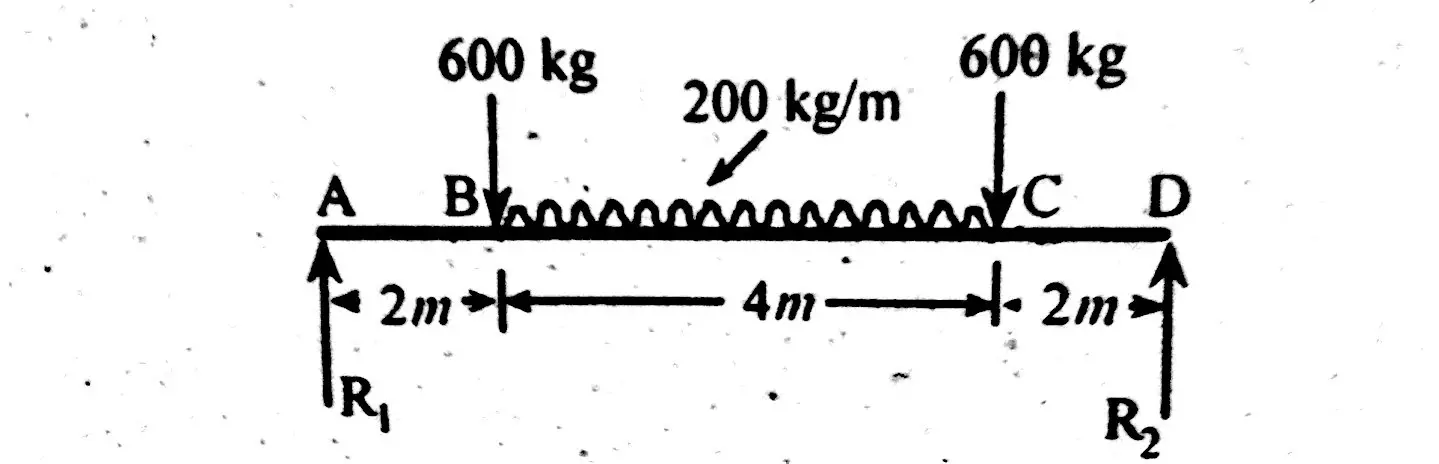
Draw shear force and bending moment diagram of simply supported beam carrying uniform distributed load and point loads. As shown in figure.
Solution
First find reactions R1 and R2 of simply supported beam.
Reactions will be equal. Since, beam is symmetrical.
R1 = R2 = W/2 = (600 +600 + 200 x4)/2 = 1000kg
Hence, R1 = R2 = 1000 kg.
Shear Force
Shear force between section A – B = S.F (A – B) = 1000 kg.
Shear force at right side of point B = S.F (B) = 1000 – 600
S. F (B) right = 400 kg.
Now shear force at left side of point C.Because of uniform distributed load, value of shear continuously varies from point B to C.
Shear force at point C (Left) = S.F (L) = 400 – (200×4)
Shear force at point C (Left) = S.F (L) = -400 kg
Shear force between section C – D = S.F (C-D) = -400 – 600
Shear force between section C – D = S.F (C-D) = -1000 kg.
Shear Force Diagram
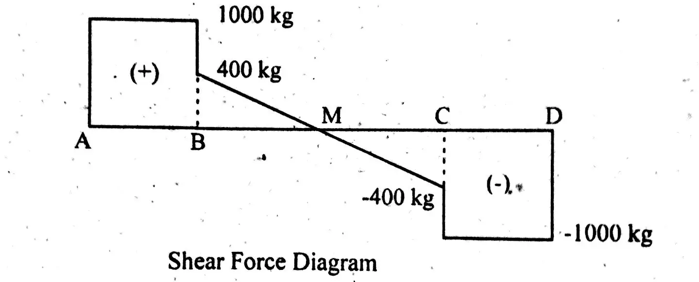
From Shear force, one can see;
- Shear force is maximum at point A and remain same until point load.
- At point B shear force value decreases, because of point load.
- From B to C shear force continuously decreases, because of udl.
- At point C shear force gradually falls, because of point load.
- From point C to D, shear force remain same, because no other point load is acting in this range.
Bending Moment
B.M will be zero at supports. i.e.,
M(A) = M(D) = 0
B.M at points B and C = M(B) = M(C) = 1000 x2 = 200 kg.m
Now, how to find maximum bending moment?
Bending moment will be maximum at point, where shear force is zero. Hence, bending moment will be maximum at mid point.
M (max) = 1000×4 – 600×2 -200×2(2/2)
M (max) = 2400 kg.m
Bending Moment Diagram
