Shear force on cantilever beam is the sum of vertical forces acting on a particular section of a beam. While bending moment is the algebraic sum of moments about the centroidal axis of any selected section of all the loads acting up to the section.
Example:
Draw shear force and bending moment diagrams of the cantilever beam carrying point loads. As shown in figure;
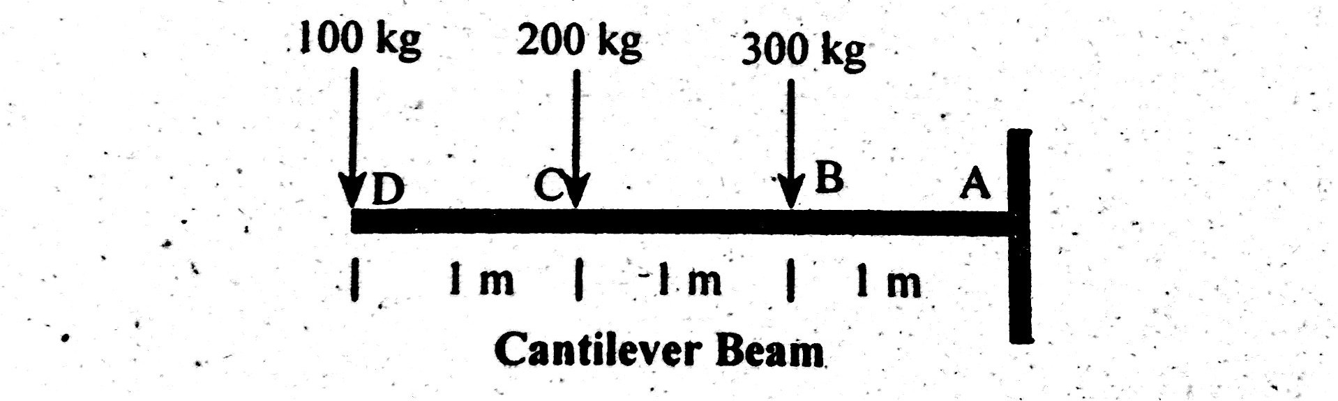
Solution
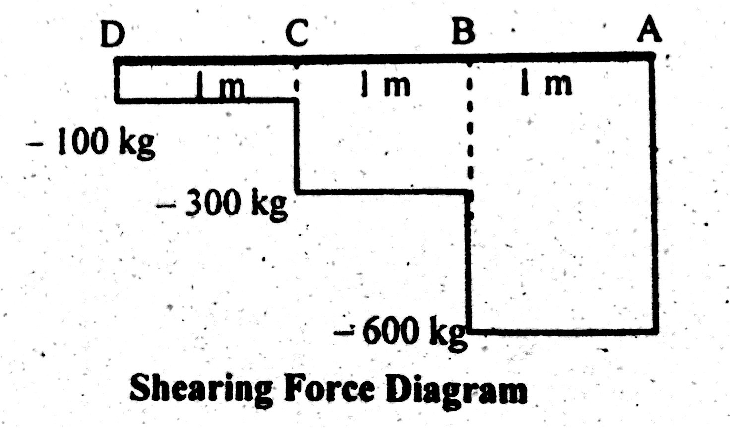
Shear Force
To draw a shear force diagram. First find value of shear force between varying loads.
Let start from left side.
Shear force Between point D and C
S.F (D-C) = -100 kg.
Shear force value increases gradually as we move towards fixed end.
Shear force Between Point C and B
S.F (C-B) = -(100 + 200 ) = -300 kg.
Now one can see, shear force between point C and B is the sum of point loads acting up to that point.
Shear force Between Point B and A
S.F (B – A) = -(100 + 200 +300 ) = – 600 kg.
One can see shear force between B and A is the sum of all point loads acting on it. This shows shear force is maximum at fixed end and minimum at free end of cantilever beam.
Shear Force Diagram
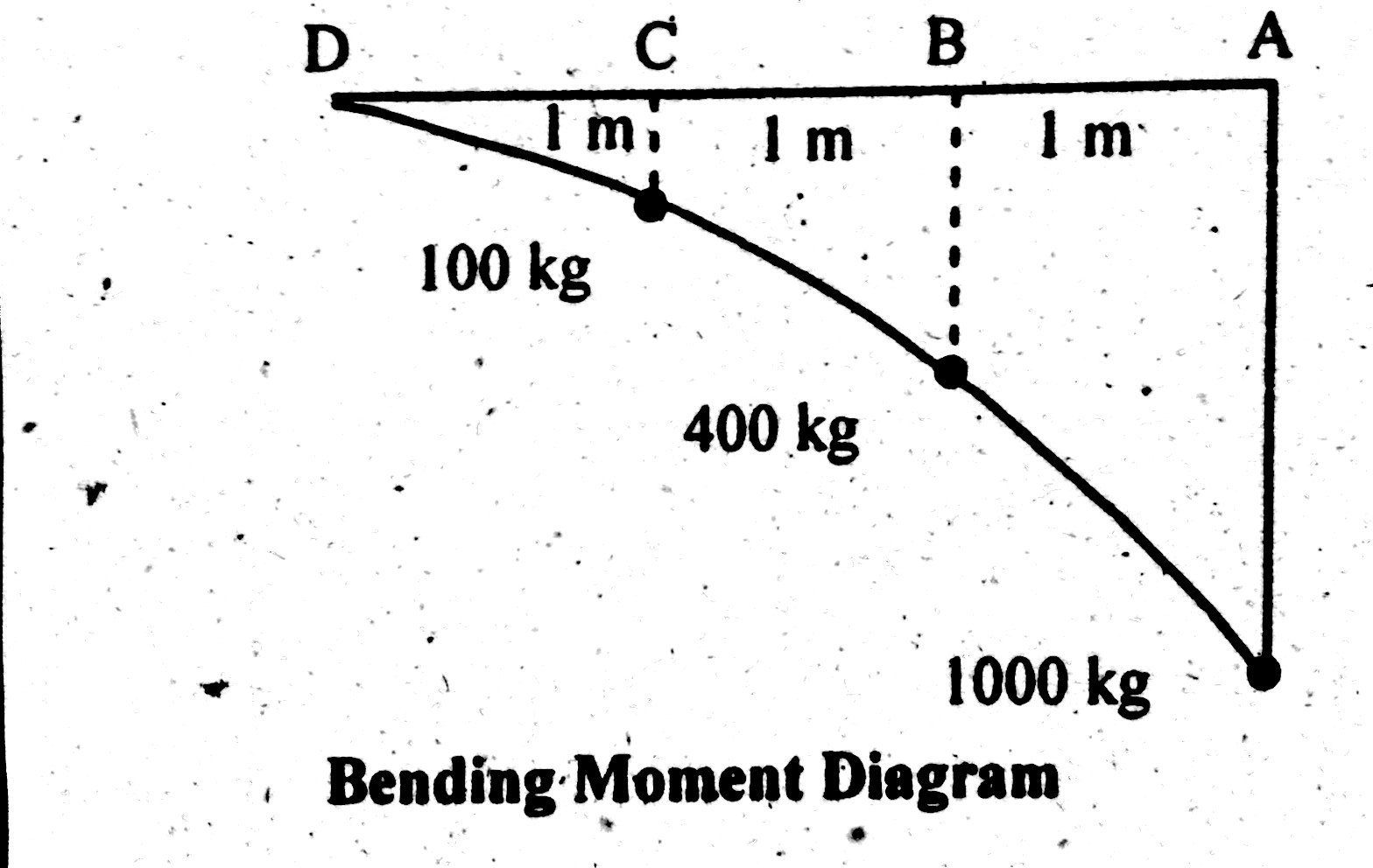
Bending Moment
Bending moment at point D = B.M (D) = 0
Bending moment at point C = B.M (C) = -(100×1) = -100 kg.m
Bending moment at point B = B.M (B) = – (100×2 +200×1)
B.M (B) = -400 kg.m
Bending moment at point A = B.M (A) = (100×3 + 200×2 + 300×1)
Total Moment at point A = B.M (A) = -1000 kg.m
This shows that maximum bending will be at fixed end. Point loads from free end transfer their bending strength towards fixed end. At the end it acts as a sum of all bending moments.
Bending Moment Diagram